Sunday, November 26, 2006

More Engine Mounts - 90% there now

Well a day spent in the garage has resulted in the engine mounts being almost completed. I've fabbed up the right hand mount. This one I decided to make in a single piece, without the necessity for a central bolt as it doesn't have the nearby waterpipe obstruction that hampered the left hand mount.


Here it is in it's 95 % complete form. I just need to trim off the excess material and fit a strenghthening gusset.


With the second mount in place, even with the bolts not tightened up the engine is pleasingly "solid" with no play or movement, careful measurement between the bulkhead and the markers for the centre point of the exhaust camshaft indicates that my fabrication is within 1mm on each side. Fab.


So now I could move onto making up the mounts for the gearbox. These will be located onto a chassis cross member. This I also had to cut out, trim down and move further forward in the chassis, in fact you can see the stubs of the old fitting that I still need to grind off the tube. These mounts are made from 1"x"2 rectangular section with some bracing tubes welded in. The plan is that these will be welded to the cross member, allowing sufficeint space for the diff mounting plates between them on both sides of the gearbox. Again I'll fit a strengthening web, as the diff is a faily hefty piece of kit and I want it very solidly mounted to the chassis.


Lastly I positioned the diff in its probable final position in the chassis. It all looks like it will line up nicely along the longitudinal axis so thankfully it looks like all my careful measuring may well have paid dividends. Once I've welded the lower mounts in place I'll be in a position to take a whole load of more measurements to finalise the rear shear plate for the chassis and the diff mounting plates that Graeme at Nova will make up for me.


So Now I need to weld these mounts in, then remove the engine and finish welding various bits that are just tacked in at the moment. Then I can clean up and paint the engine bay, and finish paint the mounting hardware. Once that is all done the engine can be permananently fitted.

Tuesday, November 21, 2006

One Side Done


Only time to spend an hour or so in the garage last night, but that was just about time enough to finish the engine mount for one side (well bodge up the first go and then finish the second one properly). It is finished all except for a small gusset to stabilise the joint, it is within a mm or so of my desired dimension so not a bad effort really in controlling heat distortion from welding.

Now for the other side, and then the floor mounts

Sunday, November 19, 2006

Engine Mounts Started

Well after a night to contemplate my engine mounting choices I made a few decisions
  1. The engine will be hard mounted... it is quite a long way from the perimeter of the chassis so I'm hoping it will be OK
  2. I'm going to externally bridge across the two mounts on each end of the cylinder head to distribute the loads across them.
  3. The front mounts will be triangulated to the existing mounting ears if possible. and the rear gearbox mounts will be fitted to the chassis floor members.
  4. The upper gearbox mounts will be connected to the main diff hardware, and I'll stabilise the diff hardware by connecting it to the rear chassis rails, thus stabilising the rear gearbox mounts.
  5. If possible I'd like to get the engine in and out easily... which means no inaccessible mountings like the cylinder head fittings on the ZX12r.

So having got it all worked out in my head, I then went into the garage, looked at the engine "in the flesh" and then spent a further 45 minutes umming and aaarhing as I reworked my ideas.

First job was to align the engine height. This was easily achieved as I simply sat it on some 2 inch box section that was positioned on the sheet of blockboad. This positions the sump about 1 inch above the main floor level, but it actually still sits in the airflow as the floor slopes upwards towards the rear. I did this deliberately to get the sump in the airflow as I think I'm going to need the additional oil cooling.

Next I was necessary to align the engine so that the output sprocket points along the longitudinal axis of the car. It took me a while to work out how to do this. But eventually I spotted that the center of each camshaft is marked on the casing. The cams will be definitely be perpendicular to the output shaft so measuring from the bulkhead chassis rails to the centre of the exhaust cam on each side of the engine and ensuring the measurements are identical should align the sprocket correctly

So I spent three or four hours today cutting welding, measuring, drilling and tapping bits of steel. By the end I had ended up with two pieces of the first mount as shown in the picture. The piece that is bolted to the block bridges the engine mounts. It has some standoff sleeves welded into each end to move the mounting away from the engine so that it can clear the water pipe union that you can see just below it. the middle boss is actually tapped M12x1.75 and has sufficient room at the rear for a jam nut to be fitted once the mounting bolt has been wound through it, that way it shouldn't come loose from the vibration. Incidentally this sleeve isn't threaded all the way through, the first 5mm or so is drilled to 12mm clearance to allow the bolt to get a start in the correct alignment. My experience with holes threaded right to the end is that they are a pain to get started, particularly if you trying to align heavy stuff like engines, but with a short section of clearance the job is much easier, having changed an engine in the paddock I'm hoping that little things like this will help a lot should I ever have to do it again. This was another reason for going for the single bolt connection on each side of the cylinder head.

The other section of tube connects to the existing mounting ears on the upper bulkhead chassis rail. The sleeve in the end is not threaded but is accurately drilled to a 12mm bore. Next I'll triangulate the end of this mount down to the mounting ears at visible on the lower chassis rail in the left of the picture. So I've made a start... just this side to finish... the other side to do and the gearbox mounts to get done. Then I can say the engine is mounted.

The threaded bushes and clearance sleeves are all made from 5/8th OD, 12 gauge wall steel tubing. One of the oddities of steel is that it is still mostly sold in imperial measurements. However it is important to buy tube that has smaller a bore than required and then drill it out to the bolt shank size. This will stop the bolts rattling in the tube and hold everything together nice and tightly. I'm using M12 bolts and 5/8th x 12g is a very handy size as its bore is about 10.2mm. This means that it can be perfectly tapped to M12x1.27 without the need to drill a pilot hole and it can of course be drilled out to 12mm for a nice snug sliding fit. Lastly it's OD is almost exactly 16mm which makes it easy to cut mounting holes in the box section tube using as stepped hole cutting bit.

Saturday, November 18, 2006

The new engine is in ...well sort of

The CRB 1000RR is in the chassis, well when I say "in" I really mean "resting in" the chassis. It's not in any way connected to the chassis but it is within the perimiter of the chassis rails.


I started off the day by cutting out the main rear cross braces, it transpires that these tubes are actually only 18guage wall thickness, and can be cut quite easily using just a hack saw. Along with the brace went the last of the remaining diff hanging hardware and the old rear brake pipes which ran across it.

Next it was time to remove the drive shafts and my usual olympic standard ineptitude came to the fore. I'd just cut the brake pipes ... the easiest\only way to undo the highly torqued hubnuts is to have a willing assistant sit in the car with the brakes firmly on while I undo the nut with a socking great breaker bar! With the brake pipes cut that wasn't going to happen so I disaasembled the inner CV joint, and removed each of the rear corners from the car completely.

It not a major issue as the suspension bushes are badly worn and need replacing anyway... but it did slow me down a bit. With the drive shafts, suspension and brake pipes removed the engine bay was very empty, so I set about it with some more rags and thinners to get rid of the last vestiges of grease... It looks a whole lot cleaner now :-), Although my finger nails dont!


Next I cut out and replaced a useless bit of steel plate that had previously been welded into the chassis. I guess this was to allow a larger diff\chainwheel at some stage, but it is plainly useless as anything other than a spacer and its lack of rigidity probabaly contributed to the bad chassis cracks that occured in the joints at both end of that particular section last year. In fact the plate has a definate bend in it which cannot be a good thing! So I welded in an over long length of 16 guage 7/8th tube that slide nicely inside the existing rails with an inch or so of additional material inside the "parent" tube on each side of the joint


So I now the car was ready to lifted onto axle stands. However before I did this I marked all the engine bay tubes with a center line to help the alignment of the new engine installation (that's what the yellow tape is for).


Then using a couple of engine cranes I hoised it into the air and dropped it down onto some axle stands and a large sheet of 3\4 block board.


After that it was a simple matter to drop the engine into the bay and use the flat bottom of the alloy sump on the blockbard to sit it level in relation to the chassis rails. So there it, I' ve just got to decide how to mount the beastie now. If you look closely at it you can see a pair of bolts sticking out of the sides of the cylinder head close to where the lifting straps connect, there is two of these on either side of the cylinder bank. plus the four holes at the end of the gearbox casing (only two are visible in the pic)

I need to think pretty carefully about mounting frame. There are a number of factors to consider and in no paticular order these are.

  • Engine alignment and centering in chassis
  • Rigid mounting or mounting with metalastic bushes
  • Output sprocket to diff input sprocket alignment
  • Clearance at front of engine for exhausts
  • Front\rear weight distribution which is affected by engine north\south positioning
  • Access to clutch\gearbox\oilfilter\fuel & coolant covers & connections
  • Suitable hard mounting points on the chassis
  • Use the engine as a stressed member to help chasis triangulation or not?
  • Height of engine\sump in relation to chassis rails
  • Allignment of diff output with driveshafts.
  • Access to gear linkage

Clearly a lot of quastions to answer, so to this end I've been canvassing a number of expert opinions.

Martin at the Kit Car Workshop always mounts engines using metalastic bushes, in case the chassis takes a biff. then the small amount of give in the bush can stop an engine mounting being broken off, plus it reducesn overall vibration. Martin also uses support frames that hold the engine from underneath, rather than an "hanging" from the mounting hardware

Ian Gray at Stuart Taylor Motorsport always hard mounts engines directly to the chassis (no bushes) but makes sure that he distributes the load by using all the oringinal engine mounts

Andy Bates of AB performance, likes to hard mount using an external frame or lattice that connects all the engine mounts together on each side of the unit. Thereby ensuring that the mounts can't move in relation to each other and "pinch" a bearing somewhere.

Tim Pell used to use bushes but now hard mounts engines.

Clearly there are lots of differnet answers to my many questions so I'm going to think about it for a bit using a bottle wine as lubricant.


nt

Wednesday, November 15, 2006

A dirty job

Today I spent a couple of hours cleaning down a generally getting the engine bay ready to have the new engine fitted. This involved large quantities of solvent and whole roll of workshop paper and much cr4p under my fingernails. However the engine bay is now pretty clean and non slimey to the touch. Which will make working in there much easier and should also improve the quality of the impending welding.

You can clearly see the scars of previous development work on this chassis, the triangulation tubes have plainly been moved around to accept different engines from time to time and the floor bracing has been modified to accept different diff\ chain wheel combinations plus there are no end of areas where brackets have been welded on and subsequently ground off when not needed. In fact one of the major tubular cross members has been removed and replaced with a plate which will clearly flex I'll be replacing this with a new tube in the hope of increasing chassis rigidity.


Incidentally the mounting ears you can see on the front chassis rails appear to be just wide enough apart that I could use them for the new side on mounts for the CBR, that could be handy.


Next job is to remove the driveshafts as these will also need changing to match the new diff, an then cut out the diagonal cruciform bracing at the far end of the chassis.


The configuration of the new diff is to have the chain wheel behind the drive shafts (in the picture the engine mounts to the left), so a chunk of the casing needs to stick our right where there is a chassis rail. My plan is to replace the tubular bracing with a shear plate not unlike the one in the pictures of the new chassis, and I've found a local company (Lasercut in Peterborough) who will make me a one off economically. So this weekend some careful measuring and a couple of hours with a CAD package should see that sorted.
Once the cross bracing is cut out I can start fitting the new engine + diff proper.

Sunday, November 12, 2006

Stripping the CBR100RR

Well did I get the new engine fitted to the car? Did I 'eck as like. I spent most of the day
clearing out an entire seasons worth of junk from the garage including the remaing bits of my previously killed ZX12r which the bloke at the dump was somewhat surprised to see arriving in his skip. I also transferred my tools back into into their winter storage in the garage where they are much more accessible than the paddock toolboxes and generally getting ready for the fettling ahead.

However I did manage to make a little progress on getting the engine ready to fit to the chassis. first job was to remove the OEM sump and dry fit the new one, this was primarily to give the engine a nice flat bottom so that it will sit up nicely while I'm positioning it in the car, and it allows it to sit nicely on my work bench. So I undid the bolts and was presented with my first view of a CBRs internals. You can also see in this picture that the new sump will save about an inch ll on the engine's overall height.

Incidentally the CBR oil pump is clearly visible as the large hole in the center of the engine.

Next I set about identifying and mark the wiring and connectors on the engine, when it arrived it was pretty much as it came of the bike, and I find it is important to go around it, removing every part\connection individually and then label it appropriately. It's really important to know where the sensors are, how the wires should be routed and so on. It's all part of the important process of educating myself about this new engine.

So if you've never seen an undressed CRB1000 RR. I've added a few shots


These are simply incredibly compact units. Considering that that lump of Ali produces some 170 bhp, and includes the gearbox, it really is an incredible piece of engineering, with an all up weight of 65kg, actually I ought to sit it in the scales to check this.

When I'd finished stripping the ancilleries and unnecessary cables away it became apparent how incredibly clean this engine is, I was hard pushed to find any grot anywhere. No oil except where I'd spilled it, no discolouration and indeed none of that gritty road grime that normally coats any engine. It maybe that this lump has really done 1000 miles On this view you can clearly see the light alloy covers that cover the emission control air inlet sytem for the exhaust. This is going in a race car so I'll not be using these, so the covers and the reed valves they contain will be removed just as soon as I work out how I'm going to block the holes to the exhausts.

On the side views you can see the two moounting holes either side of the bank of cylinders. These are tapped m12x1.25 which is a standard metric fine thread.

Accepted RGB wisdom is to tap these out to m12*1.75 which is the standard metric coarse thread, and much more easily available. In fact some guys just drill them 12mm and put a nut on the other side. So I tapped them to the larger M12 thread and wound in some long M12 bolts and a short section of box tubing on each side to that I could use my engine crane to hoist the engine and keep it in the correct orientation. Up until know I had been lifting it using the gearbox mounts and the engine only wants to lie on its back

During the initial inspection I noticed a few things.

  1. Mr Honda not only uses unique physical configuration connectors all over the wiring loom , but he helpfully colour codes them too, plus the colour codes are alse referenced in my workshop manual making identification a cinch the red one in the pic is crank angle sensor. Mr Kwak didn't make life so easy.
  2. I can find no damage anywhere except for the merest scuff on the clutch cover.
  3. The engine really is incredibly clean, and this was further borne out by a squint in the sump and into the thermostrat housing. My old Kwaka lump had deposits in the water system and it was a 5 thousand mile engine

So five things to do a a result of today.

  1. Stick it on some scales
  2. Remove the termostat, I replaced it after taking this shot as it's rubber edge acts as the mating seal for the thermo housing.
  3. Do a gearbox strip of the "cassette gearbox", this is one of the major advantages of this engine, and it should allow a gearbox change in the paddock. I just don't want the first time I do it to be in the paddock.
  4. Make some hoisting eyes for the side engine mounts for keeping in the paddock tool boxes
  5. Remove and block the exhaust air system holes.

Then once the engine bay is cleaned up, I can start the process of fitting it to the car.

Friday, November 10, 2006

Nova Diff and CBR1000 Billet Sump


I've collected my loan differential and swinging sump from Nova engineering so I thought I'd post a couple of pictures. The differential has been a bit of a TV star before when it was used on in the Discovery series "Kit Car Crisis" where a guy was building a car to come and race ion RGB.

Unfortunately the series didn't show Kit car building in a very good light and mainly served to highlight some of the pitfalls that can befall an inexperienced car builder who is badlya advised . Me, I doubt I could go racing without the vast store of knowledge and experience that my mates in Cam7 and the RGB racing fraternity happily share with me.

However none of that is relevant to the Diff.

The main reasons for changing over from the existing diff are

The new diff offers an engine driven reverse. This removes an area of constant irritation because every time you adjust the gear ratios on my existing diff (by changing the drive sprockets) you have to move the diff to retension the chain and then you have to spend a good 30 minutes readjusting the electric reverse system. This discourages me from making changes in the paddock as I know it just takes ages and I'm usually stuck for time. Plus I've been known to forget and an inoperable reverse is a common reason for RGB cars to get excluded (disqualified). Plus after a couple of seasons racing one of the key lessions I've learned is to keep it simple stupid! Any thing that requires unnecessary precise adjustment, or simply adds to your workload in the paddock is bad. You're there to race!.. Everything else is a distraction and the more of those mechanical distractions you can remove the better.

  1. The engine driven reverse actually has a chance of moving me backwards... unlike the current electric system.
  2. The current electric system which also has an alarming habit of blowing batteries by over discharging them (I've already damaged 3 like this). This means that I can probably lose some weight by going for a smaller battery too.
  3. The drive ratios are very easily changed by simply removing the blue aluminium mounting ring and bolting on a new driven sprocket (which also hides a cush drive to help reduce driveline shunt). In fact by changing both the front and rear sprockets you can get a very fine range of diff ratio adjustments although I think this would more faffing around than it's worth. Currently I can't change the driven sprocket as it is encased in enough steel to make the Forth road bridge extension so I can only change the front sprocket which is a bit of a pain and also only give quite coarse adjustment, plus my current diff's chainwheel needs replacing and some of the mounting bolts have a habit of coming lose.
  4. It runs entirely enclosed so hopefully won't spray grease all over the engine bay like my current setup.
  5. It weighs a bit less than my current setup (about 3 Kg), so I get these advanteges for no weight penalty. Although as it's a prototype unit no doubt at some stage I will pay a penalty of some sort as we hit teeting troubles. However Graham at Nova will hapily machine up some bespoke mounting brackets for me so quid pro quo. Grahams long term plan is to be able to use it as a stressed member, and hopefully over time we can reduce the weight even further.

While at Nova I also collected the billet sump pan, at this stage it is without the oil pickup so I can only dry assemble the engine, but that's ok as my current primary requirement for the sump is that it has a flat bottom. This is because tomorrow after a hefty bit of garage tidying I intend to start fitting the engine and the new diff. And having an engine that will simply sit flat on its bottom while I line it up and make the engine mounting frame around it will be a great advantage. The standard sump is pyramidal and the engine wants to do nothing but fall over at the moment.

The sump is very nicely machined from a large chunk of billet, but again it is a prototype unit.

After handling it, and looking at it for a few minutes two or three potential enhancements come to mind.

  1. It needs a small drilling so that you can lockwire the sump plug in place
  2. It need a fitting for an oil temp sender
  3. it needs an extra mounting eye in the appropriate place so that the oil filter can be lock tied to it. Oil filters tend to unscrew themselves on bike engines if not held in place with a suitable jubilee clip or tie wrap and I know at least one engine that has been blown like this.
  4. It could do with some cooling fins machining into the surfaces.

Saturday, November 04, 2006

Hoiking out the ZX12- R + Chassis Weights

I've spent the day stripping and weighing the car I wanted some solid metrics against which I can measure the changes I plan to make to the car this winter.

Remember, I'm taking the slightly odd decision to have less power in my racer, as this will allow me to step down a class, and hopefully lose a lot of weight from the car which in turn will make me more competative in Class B.

So having borrowed Steve's corner weight scales I set about taking a bunch of measurements to get a solid idea of weights of each major component. What followed was quite enlightening, well it certainly explains why the marshalls grunt a bit when pushing me around the paddock.

Firstly I weighed the car as it came back from the Birkett, fully fuelled and full of oil and coolant without driver

It weighed 555.4Kg, Gosh that's quite a lot given that Tim's Fury is 470KG in the same condition and our class weightlimits are 560 and 530Kgs respectively, although that is normally at the end of the race when we are not carrying much fuel. Still it's pretty lardy!

Secondly I weighed the car with the driver in it. And ... well you don't really want to know! But I think there's a couple of bags of spuds hidden in the car somewhere or a fragment of neutron star! Let just say that I can easily miss the weight limit by 100KG it's the rowing machine for me this winter I think.

Next I drained all the fluids, oil, water and the 25+ litres of fuel, the weight without the driver but dry with all fluids drained was 531.2Kg. So that is some 24Kg of fluids most of which was fuel. But there is probably 8 KG of oil and water in the car.

Next I removed the ZX12R, and the engine lump complete with the exhuast headers and dry sump pump, it comes in at 90Kg. Given that it puts out over 180bhp that's 2BHP per kilo, a quite impressive power to weight ratio.

With the ZX12R, diff, exhuast and Drysump tank removed the car weighs 378.4KG, so the engine, diff and lub system and mounting hardware weighs 152Kgs.

Which actually gives me a bit of of hope, as the cbr1000rr is reputed to be about 65kg, add the diff at 27kg and say 10KG for exhaust and mounting hardware and I could be looking at a saving of around 50KG on the dryweight on the car + whatever I can off load from the lard arse in the drivers seat. That's got to be a reasonable goal for the winter, to offset the slight drop in power that the new engine will have.

Incidentally the Diff weighs in at 26.8 Kg without the CV joint cups, the Nova diff I'll be using weighs about 27 dead including the cups so allowing for the mounting hardware there is probably a couple of kilos to be saved by making the effort to get it into this chassis. I wasn't going to do this as it generates a bunch of other issues, like a different handbrake assembly and changing the driveshafts so on. But with a small weight saving to be made it must be a good idea. Also after a day dissassembling the engine bay the one thing I can accurately say is that is is absolutely full of lithium CV\Diff grease. It is absolutely everywhere and yucky as hell.

Swapping to the Nova diff is worth it just to keep the engine bay clean, but the other advantages of engine driven reverse, weight saving and so on make it a no brainer.

Wednesday, November 01, 2006

Such Fun at The Birkett

Team Genesis came 8th on the road in the Birkett!

There are a bunch of Photos at Isadora Poggis' site which far better explain the concept of the Birkett than any prose I can write here. It is a unique event in uk motoracing and if you ever get a chance to compete or watch it I heartily recommend that you go along. Just remember when you are looking at the pictures that all those teams were on the track at the same time and that we were all racing each other.

I'll certainly race in it again whenever I get a chance it was so much fun!

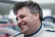
I'm 47D and a couple of specific pictures of me are at these links.
http://www.isadorapoggi.co.uk/2006/750/birkett/061028_184.htm
http://www.isadorapoggi.co.uk/2006/750/birkett/061028_234.htm


In short I had a the most fun exhilerating, entertaining and educational days racing I have ever completed. It was an absolute hoot!

I Learnt more about race craft and overtaking in one afternoon than I had accumulated in three entire seasons racing.

We turned up the day before with the express intention of getting the car scrutineered when there wasn't much of a crowd. Good job we did too, a faulty memory cell on my part meant I forgot to put the extinguisher control box in the car and a faulty earth connection meant I had no brake lights. so for the first time ever I failed scrutineering. All told it only took 15 mins to sort out but I wouldn't have wanted to do it on the morning of the race when 200 other cars were trying to get through scrutineering as well. On Friday afternoon it was quiet and we got our ticket to ride nice and quckly at the second visit.

The only other thing of note on Friday was the fact that the race van got us to the circuit with no problems whatsoever. The recent investements in new starter motor, alternator and switched to control the fridge are finally paying dividends.

Saturday

In the qualifying session I went out early and did 10 laps or so. It has been a couple of months since I raced and I wanted to get used to the relativly high speed differentials between the cars and evaluate the recent addition of the Gurney Strip to the back of the car. I'm happy to report it has made a big difference, the back end is now much less lively, in fact it is pretty planted to the track and when she does start to spin it is not an unrecoverable Snap SPin, more a gentle slide out of the backend which is nicely controllable on the throttle. All of this new stability was now reflected in very much improved grip. Previously I had been lifting slightly through the Woodcote kink in the main straight as the imbalance between front and rear end grip at this point made the car unstable and it felt like it was going to let go. With the new gurney flap it's just so planted and I can now hammer down the straight flat out all the way along. And of course improved stability and confidence meant faster times and I could do 1:11s without really trying very hard.

Remember I was also trying to learn how to overtake a Porche Carrera who was braking some 100m before I needed too, while trying to avoid a 2CV at the corner's apex which was plainly doing what seemed to be 35mph. Eventually I got brave enough to show the slower cars in fro ont my nose on the inside lines as we approached the corner so that they would know I was there. Then stuff it up the inside under braking and use the new found stability and grip to get round the bend.

The other guys in the Team, Tim Pell, Doug Carter and Steve Robinson all had pretty sucessful qualifying sessions, however Steve came in trailing oil from a failed union which caused us some concern.


The Race
Timp went out first and we started from a position of 10th on the Grid. Once underway it became pretty obvious that the pace had picked up substantially from practice. Tim moved up to 4th place and was plainly driving the wheels off his car fighting with the big block cobra in front and lapping in the 1:03s which was pretty something considering the mixed traffic they encountereed as they started to lap the rest of the field at about lap 4 or 5. Tim went on to set the fastest time of the day at 1:02:xx a top effort.

Tim came in and Doug went out and continued in much the same vein. Then it was Steve's turn, and as I was due out after Steve it was my job to be in the car, ready, helmeted and strapped in. Rady to go at a moment's notice in case he had a problem. A position some call "the hare" but I prefer the term "ready 5".

Unfortunately we lost Steve Robinson's car early in his session due to a thrown rod and blown engine, so I went out immediately and started mixing it with the different cars on the track. In this session I did 1:11s and 12s and came in some 25 laps later comepletely exhilerated I had been a bit trepidatious at the increased speed and the difficulty of negiotiating traffic. But I had such fun! Hammering along the back straight trying to find a way past three or four tin tops, all fighting amongst themselves for position and swapping lines across the track was really something. Of course it was easier now my car is a bit more planted and amongst the fastest out there but even so it was a hoot. I got overtaken by a few of the faster cars but generally I felt I had performed to my handicap marker lap.

The driving standards were exceptional, civilised & gentlemanly infact. By the end of the day I took to showing the cars in front my nose in their mirrors so that they knew I was chasing up the inside on the run in to Brooklands I had no one turn in on me all day,Ok some only gave a cars width plus an inch but that was all I now needed.

I went around Luffield up the inside of a Stock hatch and I felt I could have reached out and adjusted his wing mirror if he had needed me too. I touched Nobody all day. Top top fun.

With one car out and only three running the rest of the day was very busy with less than 30 mins between getting out of the car after your session and getting back in to be ready 5 for the next guy

I calculate I did 87 laps, 75+ of which were under race conditions, and I was mixing it with such different machinery everything from Toyata MR2s to classic Jag e types. And I got progressively much faster and more agressive during the day, and as a result I got overtaken less and less.

The Highlights were
  • Outbraking a Westie and a tin top on the inside line at high speed into Copse , Holding it on the tighter line and then making it stick on the run up to MAggots.
  • Outbraking loads of cars all day in the run in to Brooklands\Luffied.
  • Stuffing it up the inside of a tin top a Luffied.
  • Driving around the outside of Judy at Becketts.
  • A couple of four or five lap battles with big engined Morgans and an Original Whale tail Jag.

The car was glued to the track all day, the Gurney flap has really helped it's stability and I was driving the wheels of it by the end... not wanting my sessions to end.

Now I can just play around with it at the limit... a bit more throttle here for controllable back end slide or to turn the nose in, bit less throttle there to get it to tuck in. I'd heard guys talk about playing about on the limit before but I've never been able to do. I guess parallel development of b oth car and driver is the key.:-)

It was such fun and my confidence grew hugely throughout the day.
This was refelcted in my laptimes... 1:11s in fist sessions, 1:9s in the second.
Best in my 3rd sessions was 1:06.87 ONE OH SIXES! Whooo Hooo! That is 3 seconds better than my previous best.

That would put me 10th ot 11th on the last RGB grid at Sillystone a move forward of 15 places from my last position. Bejezzus and that was on old rubber too!

Today I feel I really came of age as a driver, helped in no short part by a solid stable predictable platform to drive. Hopefully higher speeds and mixed traffic will no longer phase me.

We finished 8th of 51 teams on the road which is a fine effort, but the handicap system hurt us as did the loss of one of our faster drivers so we finished 5th in class. but it was none the less a top top day.

I've been wearing a very big grin for two days as a result